Symbol Puts It All Together (Faster) with DFMA
Design for Manufacture and Assembly software helps the company to reduce assembly costs and times
At Symbol Technologies, the products are all about information. Headquartered in Holtsville New York, the company creates mobile and fixed devices that capture information, manage it in small and large computers, and communicate it over networks throughout the business enterprise. Since its founding in 1975, Symbol has introduced bar code laser scanners and decoders, wearable computers, touch scanners, and a number of mobile computing products to industries worldwide. Many of its current products combine scanners, computers, and radio frequency (RF) devices.
“Our products are at work nearly everywhere you go,” says Chris Foley, manufacturing process engineer at Symbol. “They’re checking out purchases and stocking storerooms. They’re monitoring luggage and tickets inside airports, and they’re tracking returned rental cars in the parking lots. They’re even scanning tickets at Mets games.” Symbol customers include Office Depot, UPS, McCarran International Airport in Las Vegas, and Avis.
Meeting Rules and Specs
Symbol’s products are subject to a number of requirements. The FCC regulates RF devices, and the FDA regulates laser-based devices. “And that’s just here at home,” says John Wick, manufacturing process engineer at Symbol. “When we sell a product in Europe or South America, it has to meet local standards there, as well.” Many of the devices that Symbol designs must also meet security requirements set by the credit and banking industries.
Customer specifications are just as demanding if not more so. Symbol’s products must endure being handled hundreds or thousands of times a day without failing. Some of the portable devices attach to technicians’ work-belts in manufacturing environments. Some get dropped onto carpet, tile, or concrete, or operate in freezers or in hot parking lots. Symbol designs its products to pass a battery of environmental and other physical tests. “These products are built to be tough,” Foley notes. “In final testing we drop them, we tumble them, we spray them with water, and we zap them with electricity.” Symbol even tests its products in equipment designed to simulate the rigors of shipping on a delivery truck.
All these design demands can result in a complex product with a high part count. Often assembly is complex as well. “Our products, especially the mobile ones, are restricted to a certain size. If there are a lot of parts and cables, fitting everything in can be a tight squeeze,” says Wick. A high part count and awkward fit can cause high assembly times and costs and increase field installation and service costs.
To cut costs, Symbol has decided to reduce part counts on existing and new designs. Cost cutting isn’t their only goal, however. “We’re looking to reduce cost, cut assembly times, and improve quality, all at the same time,” Foley says. “We can do all that by reducing the number of parts in our assemblies.”
Design for Manufacturing and Assembly (DFMA®) software from Boothroyd Dewhurst, Inc. (Wakefield, R. I.), helps Symbol engineers reach their product design goals. For one mobile device, they were able to reduce part count by 20 percent and assembly labor time by 17 percent. For another device, an add-on to a product already in the field, they achieved a 19 percent part reduction and a 36 percent drop in assembly labor time.
Like many Symbol products, the MC9000 is available in a number of customized options. The redesigned product had to offer the same form factors as the old model, which had a considerable installed base in the field. It also had to be compatible with existing accessories, use the same batteries, and incorporate the same key service features.
An important goal of the redesign was to standardize the assembly process for the different customized options as much as possible. As part of standardizing, the engineers hoped also to reduce part count and shorten assembly times.
The design team was cross-functional and included mechanical, electrical, and process engineers. The team followed a well-documented product development path that is a part of a larger product lifecycle management program at Symbol. “The company uses any number of metrics for PLM, including costing and scheduling,” Wick says. “DFMA analysis is our most important design metric tool.”
At Symbol, DFMA analyses of designs occur in three formal stages: Concept, Critical, and Final design reviews. In addition, less formal DFMA analyses occur whenever a team member proposes a design revision. On the MC9000 design, that happened several times weekly. Wick notes, “If an engineer asked, What happens if we get rid of these two screws?, the analyses helped us to answer that question.”
In the case of the MC9000 design, there was already an existing product. Guided by Design for Assembly (DFA) tools in the software, the engineers entered information about the assembly and answered questions about every part, evaluating the assembly processes each part underwent. The software then generated a report that included the total number of parts and assembly times.
Now the challenge was to review the part list and decide whether individual items were necessary or unnecessary. “That’s not as simple as it sounds,” Wick admits. “MC9000 had one printed circuit board for its main functionalities and another for different customer options. When we started the redesign, both boards seemed necessary.”
But were they? The more the group explored the benefits of putting the standard and optional components on a single board, the more attractive the advantages became:
- Reducing part count
- Reducing cables and cable routing distances in an already-crowded unit
- Promoting easier assembly
- Making the entire unit more rugged by reducing and simplifying connections
The team created a design for a single board. Placing features near the interconnecting connector on the board greatly reduced cable length and assembly times. The increased free space inside the unit reduced assembly times still further. Wick recalls, “We ran the first DFA report for the new design and we looked at the time savings and said, Wow.”
The engineers picked up more savings during the Critical design review. For instance, the main chassis of the MC9000 was protected by a rubber shock absorbing system that consisted of four parts, three of which had been added on in separate design reviews after mechanical testing. The DFA analysis suggested that the four parts could be combined into one. “That’s a good example of why it is worth analyzing the whole product design again when you want to add a part,” Wick points out.
During the Final design review, the team entered into DFMA the entire new bill of material that they had made for the MC9000. The software then generated a report showing the parts and estimated labor time in seconds. The results were striking (Table 1): the new design reduced part count by 20 percent and assembly labor time by 17 percent.
Table 1: MC9000 DFA results
| Current MC9000 | Final Review of New MC9000 | Percent Reduction | |
| Number of component parts | 96 | 77 | 20% |
| Estimated assembly labor (sec.) | 1038 | 865 | 17% |
Creating Product ADC
The design goals for the Product ADC product were quite different from the goals for the MC9000 because the Product ADC was an all-new design. It is a retrofit device for an existing, fix mounted product. This product entailed the possibility of mounting between one and three different modules or any combination of modules to a currently released product. This would dramatically expand the existing product functionality. This new Product ADC could be installed during our manufacturing process on the manufacturing production floor or in the field by service personnel.
The Product ADC presented two important design challenges. First, because it was an optional upgrade, the engineers wanted to keep it as low cost as possible. Second, since the Product ADC was to be field-installed, installation had to be simple. “There was one way to meet both these goals: reduce the part count,” says Foley.
Again, the team turned to DFMA analysis to address their goals. They performed the required analyses at the Concept, Critical, and Final design reviews, with additional analyses as they exchanged ideas and considered design alternatives.
The engineers made a major breakthrough during the Critical review. “Once we had an initial design, we examined assembly times and identified targets for reduction,” Foley says. An obvious opportunity for savings involved the flex cables connecting the printed circuit boards. DFMA software helped the team identify and quantify the multiple processes involved in cable installation, including:
- Creating individual flex forms to shape the cables for installation
- Installing the cables in tight, hard-to-fit areas of the product
- Plugging multiple contacts at both ends of the cables into interconnecting hardware.
Foley adds, “Bear in mind that the more parts you install on this product, the smaller your space for assembly processes becomes.” Cable installation was complicated and time consuming.
Eliminating flex cables would result in large time savings. To this end, the design team examined the possibility of combining two of the PCB boards. Results from the DFA Critical review were impressive (Table 2). By combining the PCB boards, the team reduced the Product ADC assembly by two parts—and eliminated 30 out of 34 process steps, an 88 percent improvement. Assembly labor time was reduced 30 percent.
Table 2: Product ADC Critical Review Improvements
| Concept Review | Critical Review | Percent Reduction | |
| Number of component parts | 53 | 51 | 1% |
| Number of process steps | 34 | 4 | 88% |
| Estimated assembly labor (sec.) | 715 | 503 | 30% |
The elimination of one PC board and its cables freed up valuable real estate inside the Product ADC. By using that space to reorient the remaining PC boards, the design team was able to allow for easier access to assembly points for cables and other hardware. The final DFMA review (Table 3) significantly reduced part count and reduced yet another process step. In the end, the team eliminated 19 percent of the parts, 91 percent of the process steps, and 36 percent of assembly labor time.
Table 3: Product ADC Final Review Improvements
| Concept Review | Final Review | Percent Reduction | |
| Number of component parts | 53 | 43 | 19% |
| Number of process steps | 34 | 3 | 91% |
| Estimated assembly labor (sec.) | 715 | 459 | 36% |
Reaping Results
The MC9000 has tested well and is in pre-production. It will achieve assembly time and cost savings in line with those predicted by the DFMA analysis. The Product ADC is in prototyping, with engineers evaluating a stereo lithography model. The device will be available at the end of 2005 or in early 2006.
Symbol will continue to require DFMA analyses in all its product development. The company is also introducing the software at its OEM partners, who design and manufacture Symbol products at their own sites. “We manage and oversee product development at our partners,” Wick says. “Eventually, we want DFMA to be a part of their design process as well.”
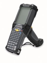
The MC9000 is a rugged, hand-held device that includes a scanner, a small computer, and a wireless transmitter for sending data over a local area network or a wide-area cellular network to a main computer. The MC9000 provides real-time information to companies in shipping, retail, manufacturing and other businesses.


